Plugs Up.
There are 2 viable
configurations when mounting a Mazda rotary in an aircraft.
The first is to mount it oil pan down, as it is in the car.
The second is to rotate the engine 90 degrees so that the spark plugs
point up and the oil pan is on the side. For
the sake of this article I will be relating everything to a tractor driven
aircraft (propeller at the front). In
my particular case, a Lancair 235. It
is not my intent to promote one orientation over the other, only to explain why
plugs up worked better for my installation.
On the surface it might
seem like extra work to rotate the engine 90 degrees however it may actually
save you considerable work when you come to mount the accessories.
In many airplanes, space is very limited under the cowl and this is
certainly the case for me. One of my biggest problems when mounting the rotary was
trying to maintain the thrust line. On
the Lancair 235 the thrust line is only 8” below the top of the cowling.
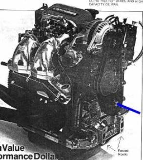
Picture 1 shows a high performance rotary with all accessories in a
“ready to run” state. I’ve drawn in the e-shaft centerline for clarity.
It doesn’t take a rocket scientist to see that the engine is a lot
taller than it is wide when all the accessories are in place.
A “box-stock”, straight out of the car rotary is even worse.
Picture 1
One thing that you
will notice in picture 1 is that there is nothing on it’s left side (other
than the spark plugs). This is
where the idea of mounting it “plugs up” came from.
I could “make” the
engine fit pan down under my cowling but that would have entailed a considerable
amount of work re-locating all the items seen in picture 1.
These include fabricating a new intake manifold (more on manifolds
further down this article. Size is
critical to performance), relocating the alternator, relocating the distributor
(more on ignition further down this article), sawing off the thermostat housing
from the water pump and re-locating it somewhere else.
PSRU’s
The most popular
PSRU’s (prop speed reduction unit) are of the planetary gear type.
These PSRU’s put the prop flange directly in line with the e-shaft thus
leaving very little room on the top of the engine.
In my case, there is absolutely no space at all.
To retain the thrust line, the block of the engine is within ½” of the
top of the cowl. Picture 2 shows
clearly how little room there is. (ignore
the starter motor sitting on top of the air filter.)
There is however plenty of space on either side of the engine.
This makes perfect sense since the airplane was designed for a 4
cylinder, horizontally opposed aircraft engine.
Flat and wide.

Picture 2
Oil
Mounting the engine
plugs up has no effect on oil flow or oil cooling to the rotors since all oiling
and cooling is accomplished with pressurized oil (all oil for all purposes comes
from the oil pump.) To put it
another way, oiling and oil cooling does not rely on gravity. Gravity is only used for oil drainage back to the oil pan.
Picture 2 shows a cut away
view of the center housing in a 13B in plugs up configuration.
I’ve drawn in the oil path for clarity.
As you can see, the oil drains back to the pan on a 45 degree slope from
the center of the engine. If you
turn the picture 90 degrees to orientate it with the pan down, you will see that
the oil still takes a 45 degree path, just in the other direction.
Both end housings operate in the same manner.
Picture 2
Picture 3 shows the
e-shaft end bearing and oil gallery when the engine is mounted plugs up.
The oil drainage hole to the left of the e-shaft bearing is the return
path for the oil being pumped to the bearing.
Both front and end of the e-shaft bearings drainage operate in the same
manner.
Picture 3
When the engine is running,
this gallery is pretty much full of oil flying off the e-shaft in all
directions. The drainage hole is
about 3/8” in diameter and dumps into the return galleries as seen in picture
2. When the engine is not
operating, a small amount of oil will remain in the end gallery, up to the blue
line that I have drawn. In
the pan down configuration, the drain hole would be at the bottom and all the
oil would drain out of the gallery when the engine is at rest.
The small amount of oil pooled in this gallery causes no problems to the
motor and is actually an advantage when mounting the 13B in an aircraft.
Airplanes tend to sit for long periods of time so the small amount of oil
that remains in this gallery, in plugs up, will keep the oil seal wet and keep
oil on the e-shaft bearing.
As for gravity
drainage back to the oil tank, I tested how much the level drops by installing a
sight gauge to the tank. The level
drops a little less than 1 quart worth when the engine is running. The amount doesn’t change measurable regardless of engine
rpm. I suspect most of this oil is
either in the rotors or is clinging to housing sides as it drains back to the
tank. Either way, it’s not an
issue and I suspect a pan down configuration would have the same level drop.
Construction of the oil
tank couldn’t be simpler. In my
case it’s just a welded up aluminum box hanging from a plate that covers where
the old oil pan used to be. The
whole thing is made from 1/8” aluminum plate.
The 5/8” aluminum line is the oil pickup.
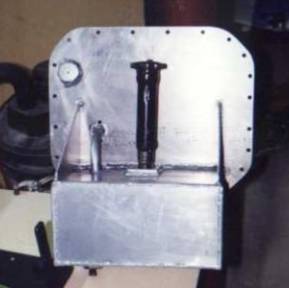
Picture 4
Water
Cooling
Cooling a rotary is
accomplished with oil and water. Oil
cools the rotors, which we’ve already discussed. Water cools the rotor housings and chambers in much the same
way as a typical V8, with a water pump pushing fluid through passages.
As with any installation, attention much be paid to not allow air pockets
to form in the passages. In either
installation, the radiator header tank must be mounted above the highest
elevation of the engine block to allow air/stream some place to collect where it
will not do damage. In a plugs up
installation, a return line should be installed from the highest point of the
block back to the header tank.
Luckily,
no modifications are required to the block to install this return line.
Mazda left holes in the end housing for extra temperature probes that can
be used for a vent line. There is
also a heater hose line that can be taped into for a vent return line back to
the header tank. In Picture 5
I’ve highlighted the return line and an alternate placement.
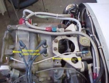
Picture 5
Intake
Manifold
Studies indicate the best
manifold for a rotary includes 18” intake runners 1.5” in diameter. As
you can imagine, this is going to take up some serious space. In the car,
Mazda wraps this manifold over the top of the engine to the other side. I
simply didn’t have that kind of space available if I mounted the engine pan
down however, if you rotate the engine to plugs up, there is all kinds of space.
I fabricated 2, 18”
long intake manifolds that worked pretty well but when I converted to fuel
injection, I bought a manifold from Racing Beat in Calf.
From all reports, this is the best performing manifold one can buy.
Needless to say, bolting it on was a breeze but there is no way this
manifold would fit if my engine were pan down.
Just have a look at picture 2 again.
Not only do you have to concern yourself with the manifold but the
throttle bodies and air filter have to go somewhere as well.
Another
nice thing about plugs up is that it keeps the fuel components far away from the
exhaust manifold.
Exhaust manifold
For
the truly performance minded, the optimum exhaust system from Racing Beat is
108“ long. Plugs up or pan down, I don’t have anywhere near the space
required for that under the cowl. The next best thing is anything that has
easy flow and minimum backpressure. My muffler is a simple box with a very
short tail pipe exiting the cowl straight down. Once again, plugs up keeps
the heat well away from other engine components. I have a small opening in
the front of the cowl to blast outside air over the manifold and out the
back/bottom of the cowl.
Ignition
At
the time I started installing the rotary, the only ignition system available was
the distributor type. I elected to use the electronic ignition distributor
over the old points system. Pan down, this ignition and distributor would
stand about 6” high over the upper cowling line. Fabricating a different
ignition was just far too much work and there would always be the question of
reliability. Thankfully, plugs up puts this distributor out to the side.
Today,
you can get distributor-less ignition systems with uses the stock crank angle
sensor (very low profile) and stock ignition coils. Buying the parts new
might keep you up at night but there are lots of used bits available at
reasonable prices.
Motor Mount
Creating a motor
mount for either orientation is a wash. Both
must be built from scratch. The
rotary has many unused threaded holes in the block to hang a motor mount to in
either orientation.